2.1 Visual Programming, Modelling and Query Languages
As Margaret M. Burnett says "Visual programming is programming in which more than one dimension is used to convey semantics" [burnett99visual]. The same is applicable to visual modelling and visual query languages. As mentioned by Paul A. Fishwick [fishwick00aesthetic] a concise metaphoric mapping with sufficient symbolism is needed for aesthetic programs or models to be executable on a computer.
Actually most software is written in textual languages. The reason is that text is easier and cheaper to cope with than images or other artistic n-dimensional data. Development in the past decades successfully introduced the graphical user interface, replacing the textual operating system shells. Performance gain of the hardware enabled this evolution. Visual query languages were developed back in the 70ies [zloof77query] and are widely accepted, e.g. in modern database systems. More recent development introduced UML [omg01uml], [rumbaugh98uml], a visual modelling language for software and business models.
While looking at concrete visual languages, it seems that the constructs are chosen according to aesthetic preferences of the developers, hardly pursuing possible general visual vocabularies. Nevertheless there are some abstract concepts for querying, programming and modelling that one has always to cope with: nesting or inclusion and association. In some languages those concepts are solved in a rigid way, i.e. the extensions and positions of the constructs in the dimensions of the languages are fixed, according to their relationships (e.g. nested boxes or circles indicating inclusion). In others, those relationships are modelled so that dimensional information is independent of relationship (e.g. arrows indicating association). Usually most languages mix both paradigms.
In Paul A. Fishwick's research [fishwick00aestetic] the concept of aesthetic programming is introduced. Based on visual approaches in programming, this concept describes a methodology for definition or modelling of new visual models. The novelty in this work is that a general methodology is proposed. The research indicates a shift in development away from ad-hoc methods to a general structured methodology of visual system development. The potential impact of those methodologies on visual languages can be compared to the impact of object oriented programming on software development. More complex tasks can now be covered, because methodologies provide interfaces and guidelines for people working together on large projects.
The following sections will present different visual programming languages, query systems and modelling languages. They are meant as inspiration for possible visual constructs and not so much comments about the qualities, advantages and draw backs of the presented languages. Usually there will not be too much in depth coverage of the semantics of those systems, the focus will be on the syntax.
2.1.1 Visual Programming Languages
Visual programming languages must be distinguished from Visual programming environments. Visual programming languages fulfil Burnett's [burnett99visual] definition and use more than one dimension to convey semantics, while visual programming environments use visual interfaces to generate parts of textual programs. Therefore systems like Visual Basic (R) are not visual programming languages as often proclaimed, but visual programming environments. They provide a classic textual programming language and user interfaces to browse the structures and constructs of projects written in this language. Usually a graphical editor for user interfaces is also provided.
The borderline between textual and visual languages is blurred and could be placed near languages like Haskell and Python, where indenting is used rather than braces to indicate block structure. If the use of n-dimensional constructs goes beyond indenting text, a normal text editor is no longer usable to develop programs. Hence visual programming languages usually need their own visual programming environments, but they are rarely mentioned in publications about visual programming languages.
Early work in the field of visual programming had "[...] advantages that seemed exciting, when demonstrated with 'toy' programs, but ran into difficult problems when attempts were made to extend them to more realistically-sized programs. These problems led to an early disenchantment with visual programming, causing many to believe that visual programming was inherently unsuited to 'real' work -- that it was just an academic exercise." [burnett99visual]. As a consequence visual programming shifted away from the domain of general purpose programming languages to domain specific and specialised languages. For those applications users are experts in the domain, but not in programming. Domain specific visual languages with a high degree of system abstraction received a better acceptance, because users did not need additional knowledge beyond their specialised domain knowledge. Digital signal processing is one of the domains where visual programming is often used.
The ideas of visual programming are usually similar to those of classical/textual programming languages. Properties like e.g. Turing completeness, side effect handling, control flow or level of descriptiveness, are relevant for textual and visual programming as well. Therefore the following overview is divided in the three categories imperative, functional and logiclanguages, which are also used to categorise textual programming languages.
2.1.1.1 Imperative Languages
Imperative programs can roughly be described as sequences or blocks of instructions/assignments. These sequences can be grouped into procedures. The entities that values are assigned to, are called variables and can be compared to named memory areas. Instructions can be computations or procedure calls. Most imperative languages provide support for primitive data types, like strings, numbers and boolean values, and also for structured values and pointers to values.
Conditions can be expressed through IF-THEN-ELSE or
CASE constructs, forking the sequence of assignments.
Sequences can be repeated, WHILE a condition holds, or
UNTIL a condition is reached. It is usually possible
to iterate over a sequence of values -- FOR every pass
the value of a variable is set to an actual iteration value (e.g. a
number) and can be accessed in the block that is iterated.
Procedures may be defined to require parameters and they may return a result value. When a procedure is called, the control flow in the calling sequence is suspended and the block of the procedure is executed. When a procedure returns (this happens when its sequence of assignments is done) the calling block continues its execution.
VIPR [citrin94design] is a visual imperative and object oriented language. The fact that the language is object oriented is irrelevant here, because this property is orthogonal to the imperative nature of this language. In "The design of a completely visual OOP language" [citrin94design] the visual imperative object-oriented programming language VIPR is presented. VIPR's semantic is inspired by C++, but it can be understood in terms of a small amount of graphical rewriting rules. Features like continuations and dynamic dispatch, which exist implicitly in C++, can be made explicit for the sake of a better program comprehension. The static view of programs as well as the visualisation of dynamic execution can be presented with the same visual metaphors.
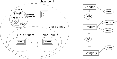
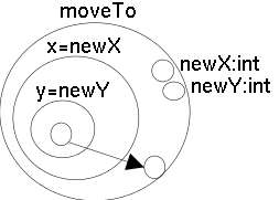
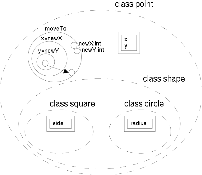
In VIPR, programs are represented as nested circles. The notation can be seen as viewing a flowchart from the point of a bead moving along the control flow lines. The nested circles can also be interpreted as segments of a pipeline with a point of view inside this pipeline. VIPR defines objects and classes by aggregating definitions of data and procedures visually. Interfaces are defined by hiding all the private methods and data. A dynamically dispatched method contains branches to all the appropriate implementations of the method, and the correct branch is selected dynamically based on the type of the object being called.
Procedures and functions are represented as sets of nested rings outside the ring of the main procedure. A procedure call is an arrow pointing to the procedure, with nodes attached representing the arguments. Nodes attached to the outermost ring of the procedure represent parameters. Each procedure must have at least one parameter, representing the continuation or the return address. The assignment of arguments to parameters is done through positional matching.
Classes and objects are shown as aggregations of methods. In essence, a VIPR class is a grouping of individual methods, each of which looks like a strand of fibre being viewed head-on. Subclasses are enclosed inside the aggregate representing the superclass. This is contrary to the usual way of modelling class hierarchies, where subclasses indicate their superclass. This implies that the superclass is modified when a subclass is defined, but the system environment can automatically deduce this for the user. Thus only single inheritance is supported (see figure VIPRcomplete).
The use of arrows in a visual environment usually leads to scalability problems concerning readability. Thus VIPR programs may be enriched by text when it simplifies the representation. Nevertheless, the semantic of the programs is fully determined through non textual components. Therefore the textual elements may be seen as documentation or syntactically restricted comments (the textual representation of visual elements is the syntactical C++ equivalent)
2.1.1.2 Functional Languages
The main difference between pure functional and imperative programming is that functional variables do not represent storage or memory areas, but represent values or functions. Once a value is assigned to a variable this value may not be altered any more. Hence the result of evaluating a function or querying a variable has no side effects, which means it will always return the same result. Therefore the control flow -- the order of evaluation -- is no longer explicitly determined in a program. Optimisation based on restructuring the evaluation order and reducing duplicate calculations can automatically be deduced. Lazy evaluation and caching of results as well as automatic parallelisation with syncronisation are advantages of modern functional languages.
Most functional languages have functions and data types as their
basic constructs. A function is defined in terms of other functions
and constructors. A constant is a function of arity 0. Inside a
function, local functions (and therefore also variables) can be
defined using so called LET or WHERE
clauses. There are various ways to express conditions, e.g. pattern
matching. Other features found in many functional programming
languages are currying (aka. 'Schoenfinkeln') and
higher-order functions.
While people concerned with imperative programming often argue that the lack of side effects is of disadvantage for optimisation, it is easy to emulate by sequencing functions taking state objects and returning state objects. This programming pattern is known as monadic programming [jones93imperative].
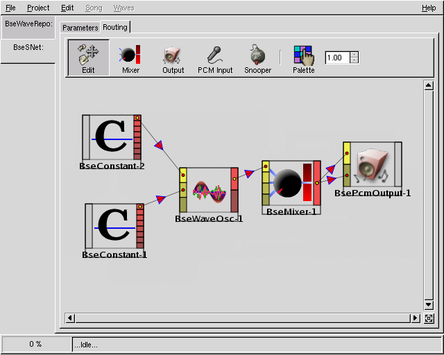
The success of visual programming in the field of digital signal processing (mentioned in the introduction of this section) is strongly related to functional programming. A simple, non technical entertainment oriented and high level system is the open source software called BEAST. BEAST can be used to build sound synthesiser networks based on simple synthesiser components. Each of those components has input and output slots that are connected by edges. Each instance of such a component can be seen as a function without side effects. This methodology emulates the classical construction of analogue synthesisers.
A general purpose visual programming language is Visual Haskell [john94visual]. The roots of the project also originate from the signal processing community.
Visual Haskell is a visual functional programming language based on the textual functional language Haskell. It is very tightly bound to Haskell. This way Haskell programs can be seen or edited in the textual and in the visual representation. The goal is to provide a visual representation to all constructs found in Haskell.
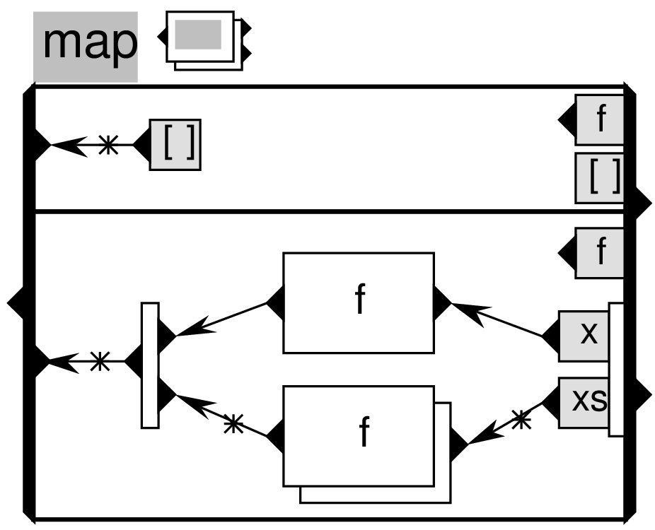
The main concept behind visual Haskell is the data-flow diagram. This seems to be generally the widespread visual view for functional programming languages. A function is defined as a box labelled with its name and optionally an icon or a visual representation. Those icons are used to provide new graphical elements for application-specific data types and functions. This way a visual metaphor is provided for a function. The visual metaphor. At one of the outer sides of the boxes bound (usually the right side) there are slots for the input arguments, at the opposite side (usually the left side) a slot for the output is available. At the inner side of the input argument slots' side, visual patterns can be attached with further slots to pass the pattern variables to concrete function bodies. This is done through arrows. Different patterns and different corresponding bodies can be stacked (separated by a line) inside the function definition box.
An icon representing a function may have a special grey box representing a visual variable for the first argument of the function. The special focus on the first argument of the function is due to a wide spread functional methodology called currying - with currying a n-ary function may be applied to m (<n) arguments resulting in an (n-m)-ary function (Thus compilers or virtual machines can break down every function application into a series of unary function applications). Functions in functional libraries are often designed so that applying something to the first argument results in a very practicable specialised function. This can be done in a cheerful way in visual Haskell, because of the visual variables inside iconic function representation.
2.1.1.3 Logic Languages
In classical logic programming neither functions nor procedures exist, only rules and facts are known. A fact is a predicate followed by an n-tuple of terms. A term can contain variables. Prolog is a widespread logic programming language. In Prolog rules are restricted to a subset of Horn clauses, disjunctions of facts with exactly one positive fact. A more popular view of the Horn clauses used in Prolog is an implication from a body (which consists of a conjunction of predicates) to a head (consisting of exactly one predicate). A special Horn clause is called fact; this Horn clause has an empty body interpreted as true. Program execution of logic programs is a kind of reasoning on the facts and rules the program consists of. The result of a program execution can be seen as proof of the rules and facts. It can be true or false, and free variables can be interpreted as being bound to the facts that fulfil the program.
Alike to the implementation of the imperative paradigm that has been presented in the section about functional programming, the implementation of functions in logic programming will be presented now. To implement functions in logic programs, rules are needed that relate the result to the arguments. To represent f(x)=y in a logic program, one may use a relation f(x,y). From the point of view of a relation, it is irrelevant which parameters are the input of a function and which are the output, thus functions implemented in logic programming languages can often be evaluated in both directions.
The execution of logic programs is usually based on resolution, which itself uses unification to either check equality of terms or provide variable bindings. A runtime system for logic programs is an inference system.
In logic programming there is no explicit control flow specification, only rules and facts. For visual programming, this means that only formulas and terms need to be visualised. Visual logic programming languages appear rarely to provide visual metaphors of those very abstract concepts, but provide domain specific concept visualisation. A visual logic language [puigsegur97from] with expressions based on acyclic graphs and sets is presented.
The visual language presented in "From Queries to Answers in Visual Logic Programming" [puigsegur97from] is comparable to Prolog in its expressiveness.
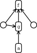
Terms are represented through directed acyclic graphs consisting of labels and variables. Variables are anonymous and are represented by circles, the parts of terms with explicit names are represented by labels written in a round box. If a term f is composed of other terms or variables, an arrow is drawn from the corresponding member to f. Sharing a variable by using multiple arrows pointing away from it, is used to represent multiple occurences of the same variable in a term representation. Because there is no explicit order for arrows pointing to a term node, terms could be interpreted as having unordered application of arguments, but this is not explicitly noted in [puigsegur97from]. The examples seem to indicate an implicit order for arrows from left to right.
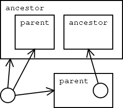
Predicates are interpreted to represent set inclusions. Therefore one argument of a predicate is omitted in arrow based application and is represented by the visual extension of the predicate visualisation. A predicate is visualised as rectangle with its name written in the top left corner. All further predicate arguments not treated as the set representing argument are applied with arrows as mentioned earlier. No explicit order is given for the occurence of the set representing variable in a textual transcription of predicates, but examples indicate that the first position is used for the implicit set representation variable. To express a subset relationship, nesting the box that represents the subset into the box representing the superset can be used. To express intersection of sets, the boxes that represent the sets are layed out in an intersecting way.
The smallest complete unit of description in this language is a diagram. A diagram is composed of various predicates and terms connected to one graph. A diagram represents a visual equivalent to a textual formula. Queries to a program (a set of formulas) can be expressed through use of explicitly marked variables. The variables are labelled by a questionmark to indicate that their bindings are to be returned as result.
The use of abstraction over one predicate argument for set representation reminds of currying in functional programming. To some extent this language supports a blend of functional and relational programming style.
visXcerpt, the query and transformation language proposed in this thesis (in the next chapter), is also a visual logic programming language. Expressions in visXcerpt are based on a visualisation of XML data, the program evaluation is based on an unification algorithm called simulation unification.
2.1.2 Visual Modelling Languages
Visual modelling is accepted more than visual programming. A reason for this could be that models are based on structure and structures are mentally coped with in a static [FOOTNOTE] : static must be understood as visually representable in 2D or 3D without temporal aspects like e.g. animation. A problem with animation is that the user needs to interact to fully understand a dynamic model., easily visualised way. Furthermore the main goal of modelling is to provide an interface for humans to understand data, thus everything intuitive is welcome to support modelling. In contrast to modelling, the main goal of programming is 'to get things done'. Even though the most important rating for programming languages is based on its readability for humans, programs need to be executable by machines. The deepest level of detail, necessary to instruct a machine without ambiguity, can be omitted in models, because human intuition fills the gap when comprehension of high level structure is focused.
Some well known modelling languages are presented now. The main purpose of modelling languages is documentation, with programs automatically derivable from models created in some modelling languages. Some systems even provide support for reverse engineering of software source code. Thus it is possible to transform back programs into models representing the structure of those programs.
2.1.2.1 ER Diagrams
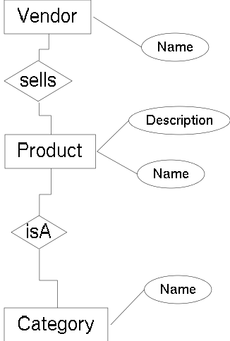
A popular diagrammatic modelling language is the Entity Relationship diagram. It is based on the Entity Relationship model. The ER model combines ideas of the network model, the relational model and the entity-set model. The main concepts of the ER model are called entity set and relationship set. Two or more entity sets are related through a relationship set. The relationships can be quantified as 1:1, 1:n or m:n relationships.
In ER diagrams, an entity set is visualised as a rectangular box and the relationship set is shown as diamond shaped box. The name of entities or name of relationships is placed inside its box. Associating entities to relations is performed by connecting them through lines. Beneath those lines the optional quantifiers 1, n or m can be placed. A later extension introduced attributes. Attributes are ovals containing names and are associated to exactly one entity set. They represent the atomic members of an entity set.
The Entity Relationship model has not been implemented in any database system, but it is commonly used during the database design phase, because it provides less restrictions and higher abstraction than most widely implemented database models. For the relational database model (and also for other models), methodologies translating the entity relationship model into the implementation model exist. Although those translations can be derived automatically, it is common to refine the translations manually.
2.1.2.2 UML
UML is the abbreviation for the Unified Modelling Language, a standart managed by the OMG. UML is used to model object oriented software (or in general object oriented architectures). Programming is not in the scope of UML. An UML model is used as plan for implementation, it can be compared to blue prints for house construction.
UML is a diagrammatic language with various diagram types. The topics covered by each of those diagram types are mostly non-overlapping, so as to make clear which diagram type to use for which aspect of the model.
The different diagram types will be presented now. A following description is based on [omg01uml] and [rumbaugh98uml].
2.1.2.2.1 Static structure diagrams -- class and object diagrams
Those diagrams are used to model object oriented aspects of the project. These diagrams are widely accepted for applications implementing UML partially. While a class diagram represents relationships and properties of classes, an object diagram is used as example for concrete instantiations.
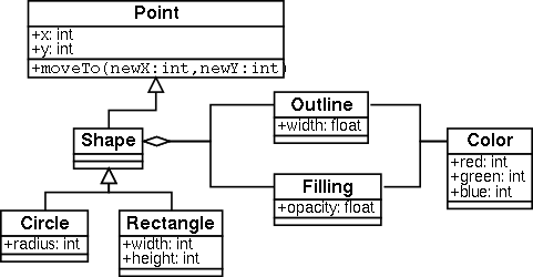
First of all objects and classes are modelled as boxes. Some visualised aspects are contained inside the boxes, others use lines and arrows between boxes. The aspects modelled are:
- Inheritance/generalisation: This is shown as a line with a big arrow head pointing towards the superclass. Usually those lines use vertical and horizontal components only. If a class generalises many classes the same arrow head is usually shared.
- Attributes/operations: Primitive attribute members and operations are contained as vertical list inside the class box.. Primitives are usually strings, boolean values and numbers. For other members, association or composition is used. Operations may contain parameter lists enclosed in parentheses. It is a purely textual feature.
- Types: The type of parameters, attributes and operations is appended, separated by a colon. It is a purely textual feature.
- Visibility: The visibility of a member is modelled by prepending a textual symbol like + for public and - for protected. Standard colour icons for the visibility attributes exist. It is questionable if those icons make the visibility aspect a non textual aspect, just because they happen not to be part of the usual font sets, after all it does not provide a new dimension.
- Association/composition/aggregation: Those features are used for non primitive members of classes. They are mainly represented as lines between two classes. They may be directed and a name must be associated to such a line. The name is usually written below the line. Composition and aggregation are special cases of associations and are shown through diamond arrow heads either filled (composition) or hollow (aggregation).
- Multiplicity: On both ends of an association the relations multiplicity may be written in textual form..
2.1.2.2.2 Use case diagrams
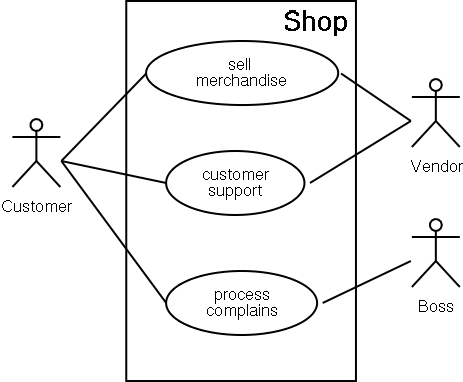
Use case diagrams are used to model relationships between use cases and actors. They are only for documentation purpose, no automatic program generation is known that benefits of use case diagrams.
A use case diagram is a graph with use cases and actors as nodes. The arcs are so called use case relations and actor relations. Actors are drawn as stick-figures with labels below, use cases are abbreviated by ovals with labels inside.
2.1.2.2.3 Interaction diagrams
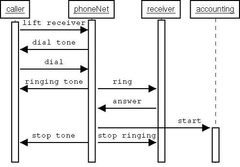
Interaction diagrams are realised through sequence diagrams. A sequence diagram is used to model the life line of an object, the activation and the message passing. Sequence diagrams are two-dimensional diagrams: one dimension (usually the vertical) is used to display evolution through time, the other to distinguish between different objects. Therefore an object is a vertical line with a thick bar on the line indicating the life line of the object. Message passing is modelled by arrows pointing from one object to the next at a certain state transition on the life lines of both objects. When message passing is instantaneous, the arrows are horizontal.
2.1.2.2.4 Collaboration diagrams
A special case of object diagrams are collaboration diagrams. They provide links between objects. They represent message passing between objects and actors. Therefore also stick men are allowed in collaboration diagrams. The expressiveness is comparable to the sequence diagram without temporal aspects.
2.1.2.2.5 State chart diagrams
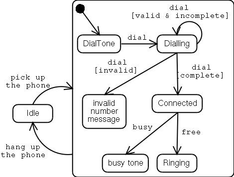
A state chart diagram can be used to describe the behaviour of an object. It is a graph of states as nodes and state transitions as directed edges. A state is displayed as rectangle, an edge as arrow. A node is labelled with the state name inside the bounds. It may also be divided in two areas where the first contains the name and the other an activity in process while in this state. Edges are labelled with a name and optional preconditions (in textual form). A special state, the start state, is a little empty circle. An end state is a double bordered circle. State diagrams can be nested hierarchically, indicating sub state machines. Entering a sub state machine begins at the starting state of the sub machine. Reaching an end state means leaving a sub state.
A special case of a state chart diagram is the activity diagram. An activity diagram has mostly actions (a UML-term) as states. It represents some kind of flow diagram and has therefore some visual constructs for handling conditions, like a diamond shaped box for conditionals and plates for merging control flow.
2.1.2.2.6 Implementation diagrams
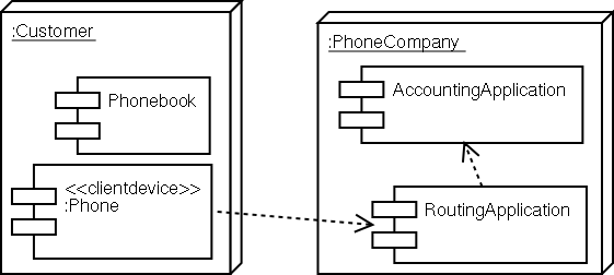
Implementation diagrams show aspects of the concrete implementation. There are two types of implementation diagrams:
- Component diagrams: They show the dependencies of implementation components. A component diagram is a graph of components connected through edges representing simple dependency, containment and implementation relationships
- Deployment diagrams: They represent the configuration of runtime objects like processes, and objects that are part of them. A deployment diagram is a graph of nodes representing processes with communication associations as edges. The processes are displayed as bevelled boxes containing component diagrams.
2.1.2.3 UML's four layer meta model
All those different visual diagrammatic languages in UML are based on the same four layer meta model. It consists of:
- meta meta model: The infrastructure used to model meta models. It is mostly the definition of a graph
- meta model: Meta models are the languages described above (like class/object diagrams, collaboration diagrams,...)
- model: A model is the output of the concrete use of the former meta models, or in terms of programming languages: modules and classes.
- user objects: User objects are instances of former classes.
UML itself mostly covers meta models. Research work about visual meta- meta modelling can be read in [fishwick00aesthetic].
2.1.3 Visual Query Languages
As read in [catarci93fundamental] "Visual Query Systems (VQLs) may be defined as query systems essentially based on the use of visual representations to depict the domain of interest and express the related requests." Among the first visual query languages is Query By Example (QBE), which is still quite popular in education and whose descendants can be found in popular commercial database systems like Microsoft Access. Common to almost all visual query languages is the fact that they are tailored for the casual user. This is not surprising, because casual users have a big demand for querying databases easily. Thus a lot of visual query languages for almost all data models have been investigated, with the goal of achieving general acceptance of their underlying data model.
A further property among visual query languages is the use of patterns. One advantage of pattern based queries is, that the same formalism can be used to express the data and the core of the query itself. For visual query languages fulfilling the former definition of [catarci93fundamental], a visual representation of the data reveals the core of the visual queries without extra effort. Casual users benefit from this consistency, because after understanding the structure of the data model, they do not need to learn a new formalism for the query language.
In [cruz90a], the connection between graphs and most applications is mentioned and a query language based on graphs is proposed. This generalisation leads to a query language that could be used in many different domains. With the casual users in mind, the use of a less abstract visual formalism that is nearer to the desired target application domain is advisable. In [fishwick00aestetic] a methodology for support of project specific aesthetic is described, but the design of a new VQL specially tailored for every new project is possibly not feasible. The right balance between abstraction (and hence application independence) and concreteness (and therefore intuitiveness) is an unsolved problem that is possibly only solvable through intuition and experience.
2.1.3.1 Kaleidoquery
The short description given here is based on [murray98kaleidoquery].
Kaleidoquery is a visual query language for object databases. It is a visual syntax that is back-ended by the textual query language OQL. The main philosophy behind Kaleidoquery is a filter flow metaphor. This can be compared to a functional paradigm. Kaleidoquery is modelled towards the needs of casual users that want to create ad-hoc queries. The iconic nature is useful for users not aware of the database schema -- they can deduce it from the visualisation.
A query can be explained as a chain of filters, with all database extends passing through this chain and being successively reduced until the intended result is left. The first element of this filter chain is an icon representing a certain class in the database. The database author is urged to provide icons to database classes. The chosen icon is the lowest member of the filter structure. For a projection of some attributes, a vertical arrow is used pointing to an oval with the attributes that should be projected. A filter network without projection as last filter step has no output. This is useful for joins, that are explained later.
Further simple constraints (like less, equal,...) can be placed in textual notation on this uprising filter path. To express conjunction of constraints, all constraints are attached vertically by arrows. For disjunctions, the filter flow is split into many parallel vertical filter flows, each strand representing one disjunct. Horizontal arrangement of disjuncts and vertical arrangement of conjuncts is quite common in visual languages. Negation is expressed by inverting the corresponding simple constraints colours.
Joins are expressed by parallel filter expressions sharing a simple binary constraint, like equality. One side of the equality is then located in one filter while the other side is in the other subfilter. A self-join is also possible, when two arrows are drawn from one class oval.
Object oriented databases may store complex structures where objects may contain other objects as members. Refining a query based on certain members of selected objects along the filter flow is a common operation. Shifting the selection to the members of an object is called navigation. Navigation is represented by a horizontal arrow with the name of the member written above it.
In object databases a common operation is checking for membership of objects. For this purpose a curly horizontal arrow with the word member is used. The same curly arrow is also used for the for all and the exists quantifiers found in OQL.
Further expressions like functions, grouping and ordering constructs are expressed by wrapping the ovals with further ovals. The corresponding operation is included in the wrapping oval. This corresponds to the nested term structure of the textual OQL counterparts.
Kaleidoquery has a very imperative nature in the sense that the queries are refined step by step. The user has to be aware of query optimisation while using constructs like conjunction. For example using more restrictive constraints at first is better than using them later in the filter flow. Generally, the use of edges (arrows in Kaleidoquery) tend to render cluttered views for big programs, because of line crossing. However, even big Kaleidoquery programs do not seem to get cluttered. A reason could be that edges are not used to express structure.
2.1.3.2 Query by Example
As example for a visual descriptive query language QBE will now be explained. The description is based on [zloof77query].
QBE (short for Query-by-Example) is a database management language. The base idea is that the user fills in examples of the data he/she intends to modify or query. The underlying data model for QBE is the relational data model. Because relational databases can be seen as a set of tables, the example queries edited by the user are tables.
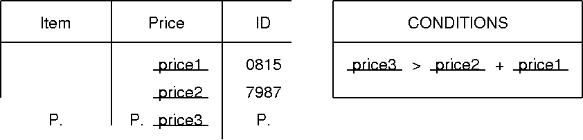
QBE is a visual query language language, because it relies on tables which provide arrangement of information in two dimensions. Except underlined text (to indicate variables), further constructs of QBE are purely textual.
In QBE a query starts with an empty table skeleton based on the
schema of the data. The user may now fill in fixed values for
constraints of the result data. For different alternative
constraints, more (implicitly OR-ed) cells are filled into
the table. The result of executing such a query is a table
containing only tuples found in the database fulfilling the
constraints. The result schema is the same. To return data in
different schemata, the user may use the keyword P.
(for print) in columns relevant to the result.
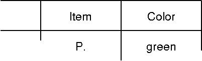
Variables have a name and are represented by the underlined
name. A P. can be prefixed to the variable name if the
table is also to be printed. In QBE it is considered good
programming style to choose names that can be seen as example
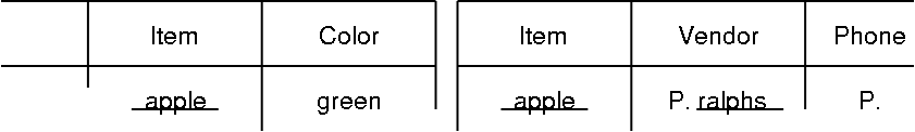
instances of the desired variable bindings. The same variable can
also be used in different database tables within a query - this
pattern is called link. Thus joins over different relations can be
formulated. Temporary result tables can be introduced. They may
contain only variables of queried tables occurring in the same
query.
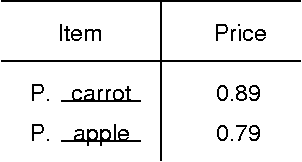
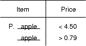
For further qualification of variables or constant values,
inequality operators and negation can be used, as well as
arithmetic expressions. There is also a so called
Conditions box: expressions over variables, arithmetic
expressions, equations and AND and OR
concatenated expressions can be placed here. It is intended to be
used when conditions are difficult to express in table cells.
For grouping and aggregation further keywords are provided:
-
ALL.prevents omission of duplicate elements in the result, -
CNT.counts the matching tuples, -
SUM.adda all matched numeric values together, -
MIN.andMAX.get the minimum/maximum of the matched values and -
AVG.calculates the average of the matched numeric values.
To be able to fully manage a database, not only querying but
also inserting, deleting and updating is necessary. The keywords
for this are D. for delete, U. for update
and I. for insert. I. can also be used to
create new tables in conjunction with keywords describing the valid
database types. These operations are used similar to the print
operation.
QBE has been used as conceptual framework for many successful commercial database systems like MS Access. For a measure of feature completeness and for the sake of comparability, the expressiveness of query languages for relational databases are compared to the relational algebra or to the tuple calculus (which provide the same expressiveness) : QBE can directly be translated into the tuple calculus and is hence as expressive as for example SQL, but it is much easier to use especially for casual users -- the knowledge about filling in forms is wider spread, than the knowledge about textual database languages.
2.2 Non visual XML Query Languages
XML has been proposed by the W3C as resort out of the so called browser war, initiated by the rivalling companies Netscape and Microsoft. Both tried to extend the document standard HTML with incompatible extensions in form of new markups, in the hope to establish them as new de-facto standards, urging the market to accept their product as the better solution. While the pureness of HTML as a generalised markup language is vulnerable to feature extensions, the generic markup language XML is destined as meta language for HTML-like languages, and therefore encourages application developers to define new markups. Thus the former violations of HTML got transformed to productive extensions encouraged by the new standard. At the same time the extension task was shifted from the browser developers to the web site authors, urging the browser developers [FOOTNOTE] : An interesting aspect of this competence drift is that the browser developers are all members of the corresponding standardisation bodies. Therefore they seem interested in preventing new power struggles as seen in the browser war. to provide the generic extension mechanisms.
Infrastructure for the proposal of new languages without compromising standards was only one aspect of the escape out of the browser war. Infrastructure to provide implementations for those potentially infinite new languages is the other task. Therefore one of the first subsequent requirements after the XML core definitions, was the ability to translate XML based languages into other languages like e.g. HTML. This requirement was first fulfilled by XSLT, a navigational transformation language inspired by functional programming and query languages.
XML's generic nature soon attracted the attention of the database community -- XML is in fact an instantiation of the semi structured data model, originating from the database research community [abiteboul00data].
The high expressiveness of XSLT also led to applications that originated from database domain, but this was done (and is still done) mainly to ride the hype of XML as new technology. XSLT is tailored towards document processing and often cumbersome if used as query language. Thus a query language had to be proposed for XML. Nevertheless XPath, the central aspect of XSLT, got quiet popular and was therefore used as inspiration while developing XQuery, a new XML query language. In fact XQuery incorporates a new XPath version and at the same time is the root of its definition. This is sensible for the sake of concept compatibility throughout the XML community.
The following section will describe XPath, XSLT and XQuery in more detail. After that Xcerpt, a completely different approach to the task of transformation and querying of XML, will be presented. Opposed to the navigational nature of XPath based languages, Xcerpt is a pattern based descriptive language.
For proposal of a good visual XML query language it is useful to look at existing textual query languages, to be able to adopt popular aspects or paradigms for querying XML. The comparison and the former section about visual query languages will hopefully be enlightening for preferring the pattern based approach as base of a visual XML query language.
2.2.1 Navigational queries with XPath, XSLT and XQuery
The following query languages, as well as XML, are standards proposed by the W3C. The W3C's is a standardisation consortium. W3C standards are called recommendations. W3C recommendations usually precede concrete products. This process differs from the work of other standardisation organisations (like e.g. the Internet engineering task force -- IETF) that usually standardise existing technologies. The W3C consist of members from industry and academia.
2.2.1.1 W3C's Standardisation Process
The W3C's standardisation process is transparent and can publicly be followed by everyone on the WWW. Only members are allowed to contribute to the standardisation process. A recommendation is the final and stable version of the standard emitted by the W3C. Such a recommendation is likely to be integrated in various related commercial products, because often the leading companies working on concerned topics are members of the W3C and are also the main contributors. The W3C's recommendation process passes through the following stages (as defined in the W3C Technical Reports and Publications page)
- Note : A Note does not represent commitment by W3C to pursue work related to the Note
- Working Draft : These are draft documents and may be updated, replaced or obsoleted by other documents at any time. It is inappropriate to use W3C working drafts as reference material or to cite them as other than "work in progress".
- Candidate Recommendations : A Candidate Recommendation is work that has received significant review from its immediate technical community. It is an explicit call to those outside of the related Working Groups or the W3C itself for implementation and technical feedback.
-
Proposed Recommendation : A Proposed
Recommendation is work that
- represents consensus within the group that produced it and
- has been proposed by the Director to the Advisory Committee for review.
- Recommendation : A Recommendation is work that represents consensus within W3C and has the Director's stamp of approval. W3C considers that the ideas or technology specified by a Recommendation are appropriate for widespread deployment and promote W3C's mission.
2.2.1.2 XPath
The navigational aspect of XSLT and XQuery is expressed through XPath expressions. XPath has reached the state of a W3C recommendation. XPath should not be seen as a language on its own, but rather as query expression for hierarchical data, like regular expressions for textual data. Although simple query tools for evaluation of XPath expressions on XML data [FOOTNOTE] : Xmllint's shell mode can be used for this purpose. Xmllint is part of the libxml library, hosted at exist, it is usually considered to be a component of a host language. XPath is part of XSLT and XQuery.
An XPath expression is applied to so called XML contexts and returns a (maybe empty) list of XML contexts. An XML context is a node or location inside an XML document. An XPath is a sequence of selection primitives and conditions, each applied to the selected contexts of the preceding selection primitive. The primitives are instances of the so called Axis and are the simplest possible XPath expressions. Those axis provide the ability to select
- named children or any child of a context node
- the parent node of a context node
- the previous/following nodes of a context node in document order [FOOTNOTE] : Document order describes the order in which the nodes -- or least their closing tags -- occur in a textual XML representation. For a tree view of XML data this corresponds to the order of a depth-first left-to-right traversal of the tree.
- the previous/following sibling nodes of a context node
- named (or any) children or descendant at any depth below a context node
- a context node itself
If a path primitive (or a whole XPath expression) is applied to a list of contexts, the results of applying the XPath to each context are concatenated. Conditions are either boolean functions operating on contexts or further XPaths. If a condition is an XPath it is interpreted as successful if the XPath's result is not the empty list.
/html/body//a[    contains(./text(),"Xcerpt")
              and starts-with(./@href,"http:")
             ]
Although XPath is defined to process tree structures, nothing enforces an implementation to work on physical tree structures. There is ongoing and very promising research [olteanu02xpath] about processing XPath expressions on streams of XML events -- known as SAX streams. This has the advantage of not having to manage an in-memory representation of the XML document. This is highly relevant for processing very large databases. It is even possible to support approximated queries on infinite streams.
2.2.1.3 The transformation language XSLT
XSLT is the first XPath based language proposed by the W3C and has reached the state of a W3C recommendation. XSLT is intended to be used for transformation of XML documents into other XML, HTML or even plain text documents. A template based approach is used. An XSLT stylesheet is applied to a document [FOOTNOTE] : Although applied to only one document, it is possible to specify the use of further documents either as input through an appropriate XPath-function, or as included templates. and returns a new document.
Some major components of the visXcerpt prototype have been implemented using XSLT. For the reader unfamiliar with XSLT and interested in studying the implementation of the prototype, XSLT is explained in more detail here. Nevertheless, XSLT is mostly irrelevant for the design of the visXcerpt language itself.
The whole process of transformation is driven by recursive
application of templates. The selection of the context and the
restriction to the template to apply to the context selected is
expressed in XPath. Every template has an XPath expression that has
to match with a context in order to be applied. If many templates
match the same context, various precedence rules determine wich
template is actually chosen. The template consists mainly of a
portion of XML content [FOOTNOTE] : A portion can be plain
text, or any number of elements. It is not necessary that there is
only one root element, but all elements have to be well formed. It
is therefore not possible to open tags in one template application
and close them in another one. which may contain hooks for
further template application. Those so called
apply-template elements establish the recursion step.
They have an XPath expression for selection of the next recursion
step's context. The syntax of the XSLT language itself is XML
based.
With the recursive template mechanism, generating new XML content based on existing content is defined. Further aspects of XSLT are:
-
Including data from the input document:
Textual data can be included with the
value-ofelement. An XPath expression is supplied to select the context that is to be included. If the expression evaluates to more than one context, only the first one is considered. If the context is not a text-node or an attribute, nothing is copied. To copy an element with all its attributes, thecopyelement is used.Example : XSLT-1... <xsl:template match="a"> <xsl:copy select="."> <apply-templates select="*|text()"/> (see <xsl:value-of select="./@href"/>) </xsl:copy> </xsl:template> ...This example promotes the template, apply-template, value-of and the copy elements of XSLT. A template is presented that extends HTML hyperlinks with a textual representation of the URL they point to. The a-element is copied with all its attributes, the content is recursively processed and a "(see http://...)" is appended. -
Variables and parameters: To be able to
transfer data from one template invocation to a subsequent template
application, templates can be parametrised. Therefore in a
template, named parameters with default values can be defined. A
template application can then set those parameters to other values,
but it is not forced to. Assignment to parameters is restricted to
the template application, and further applications of the same
template are not affected by the assignment. It is therefore
considered to be a side effect free assignment, comparable to
let expressions in pure functional programming languages.
Variables are similar, but may only be defined and used inside of templates, or globally inside of the stylesheet. Template variables are not accessible outside their containing template; global variables are accessible in the whole stylesheet.
Example : XSLT-2<xsl:stylesheet version="1.0" xmlns:xsl="http://www.w3.org/1999/XSL/Transform"> <xsl:variable name="TITLE"> <xsl:value-of select="/html/head/title/*"/> </xsl:variable> <xsl:template match="/"> <xsl:variable name="COUNT"> <xsl:value-of select="count(//h1)"/> </xsl:variable> <h1>Index</h1> <xsl:apply-templates select="//h1"> <xsl:with-param name="COUNT"> <xsl:value-of select="$COUNT"/> </xsl:with-param> </xsl:apply-templates> </xsl:template> <xsl:template match="h1"> <xsl:param name="COUNT">???</xsl:param> <xsl:apply-templates select="*"/> ( <xsl:value-of select="position()"/> of <xsl:value-of select="$COUNT"/> ) in <xsl:value-of select="$TITLE"/> </xsl:template> </xsl:stylesheet>Parameters and variables are used to transport values accross contexts. TITLE is a global variable. It is invoked in the third template by its name $TITLE. The second template passes the parameter COUNT to the third template. COUNT has the default value "???" if the template is called without parameter. -
Further conditions: The template application
according to an XPath selection and the template choice according
to a matching XPath is a powerful conditional. It can be compared
to the guard based conditional of modern functional languages like
Haskell or
Clean [FOOTNOTE] : Haskell's guards are described in the
"gentle introduction" in the section about pattern matching
semantics at
http://www.haskell.org/tutorial/patterns.html#sect4.1.
Nevertheless, it is sometimes useful to be able to restrict
template application, and therefore have the application hooks
surrounded with conditional constructs. For this purpose the
ifconditional can be used. The test is either a boolean test or an XPath expression that has to be productive to be interpreted as true expression. There is no else to choose between two alternatives. For choices there is achoiceconditional with the same semantic as the widely knownswitch/caseconditional in C or Java.Example : XSLT-3... <xsl:template match="h1"> <xsl:copy> <xsl:if test="contains(text(),"Xcerpt")"> <strong>[RELEVANT] </strong> </xsl:if> <xsl:apply-templates/> </xsl:copy> </xsl:template> ...This template can be used to prefix an annotation "[RELEVANT]" in h1 headings containing the ord Xcerpt. -
Namespaces and XML abstraction: XSLT is an XML
based language, therefore it uses XML elements as syntactical
elements. The construction patterns are also in XML syntax. To be
able to distinguish between construction patterns and XSLT elements
the XML namespace mechanism is used. To be able to use
XSLT-elements as construction patterns, there exists a so called
namespace-aliaselement that defines a namespace to translate into the XSLT namespace in the output element. This mechanism was widely used for the prototypic implementation of visXcerpt, which is partly implemented using XSLT.When it is inconvenient to use XML patterns, because e.g. an element name is parametrised, or because only attributes are to be created in a template, there exists an abstraction over XML elements. The XSLT elements
attribute,element,text,commentandprocessing-instructionare defined for this purpose. The content of all of those elements is interpreted as the corresponding child content or value,attributeandelementhave an attributenamefor the corresponding names of the constructed components.Example : XSLT-4... <xsl:element name="a"> <xsl:attribute name="href"> http://www.xcerpt.org/ </xsl:attribute> <xsl:text> The Xcerpt Homepage </xsl:text> </xsl:element> ...This is the part of a template. It produces a HTML hyperlink to the Xcerpt homepage by using the XML abstraction of XSLT. -
Defining functions: Functions as known in
programming languages are very similar to templates. Applying
templates is in fact like having a function applied to some XML
content from the input document and having the return value
transferred to the output document. To be able to call functions
from inside other functions, it is possible to give templates a
nameattribute and to use thecall-templateelement with the name of the template to call. This feature is mostly used to centralise functionality used in different places of the transformation stylesheet.Example : XSLT-5... <xsl:template match="body"> <xsl:apply-templates/> <xsl:call-template name="footer"/> </xsl:template> <xsl:template name="footer"> <hr/> (c)2003 - Sacha BERGER. </xsl:template> ...
A function named footer is provided to insert a copyright note in various situations. The first template calls the function defined in the second template. -
The
for-eachelement: Thefor-eachelement has aselectattribute containing an XPath, and a construction pattern as content that is applied to the data matched by the XPath expression. It can be compared to an anonymous function (a lambda function) in functional programming languages. Thefor-eachexpression is an anonymous template applied to the Xath expression of itsselectattribute.Example : XSLT-6... <xsl:template match="body"> <body> <h1>Index</h1> <ol> <xsl:for-each select=".//h1"> <li> <xsl:apply-templates select="*"/> </li> </xsl:for-each> </ol> <hr/> <!-- CONTENT --> <xsl:apply-templates="*"/> </body> </xsl:template> ...This template may be used to enrich the body of a HTML document with an index list containing all h1-headings found in the original document. -
Reordering data: Using the
sortelement inside anapply-templateor afor-eachelement it is possible to sort the items matched by the XPath. It is possible to sort lexically, numerically and language dependent. Using theselectattribute it is possible to specify an XPath expression relative to each item, based on which the sorting has to be done. -
Modularising templates :The
importelement is used to import templates defined in external stylesheet documents. In case of conflict with locally defined templates, the local ones have higher precedence. Theapply-importselement is used inside templates as application hook restricted to imported templates. It has no XPath expression and therefore is only applicable to the actual context.
XSLT is a widely accepted W3C recommendation with several implementations available. It has reached the W3C status of a recommendation which means that the standard is considered to be stable. The expressiveness of XSLT is comparable to the expressiveness of a general programming language, because it is Turing complete [FOOTNOTE] : The Turing machine markup language TMML (found at http://www.unidex.com/turing) can be processed with XSLT, which demonstrates the turing completness of XSLT. A further proof for Turing completeness can be found in . Nevertheless, it is not convenient to use XSLT for general programming tasks, because of the rigid information flow from input document to output document. The Turing completeness of XSLT ensures that all transformation requirements can be achieved with XSLT, but the drawback is that there is no termination guarantee for the transformation process.
2.2.1.4 The XML query language XQuery
Like XSLT and XPath, XQuery [w3c02xquery-wd] is a language definition maintained by the W3C. It has not yet achieved the state of a recommendation, it is filed as a working draft. This indicates that XQuery is work in progress.
From a sloppy point of view, XQuery looks like a mix of XPath and SQL [fatdog01quick]. From an academic point of view "XQuery is a typed, functional language for querying XML" [wadler02xquery]. Opposed to XSLT, XQuery does not use an XML syntax exclusively, although construction patterns can be written as XML portions. As proven in [kepser02proof] XQuery is Turing complete.
2.2.1.4.1 XPath and XQuery
In the most simple form, XPath expressions are already XQuery programs. The XPath standard that is included in XQuery is XPath2, which is also a working draft. While comparing the XPath2 working draft [w3c02xpath-wd] with the XQuery working draft [w3c02xquery-wd] it is apparent that both standards are strongly related. As described in [wadler02xquery], it is possible to express all XQuery programs in a reduced language called XQuery core. XPath expressions are not part of this reduced language and can be rewritten using the core language.
2.2.1.4.2 FLWR Expressions
Beside XPath, the most important syntactical construct is the so called FLWR [FOOTNOTE] : FLWR is pronounced like expression. FLWR stands for for, let, where and return. The meaning of those four parts will be roughly explained now:
for $b in document("http://www.bn.com/bib.xml")//book
  let $e := $b/author[contains(string(.), "Suciu")]
  where exists($e)
  return
    <book>
      { $b/title }
      { $e }
    </book>
-
for : This part is written like
for
$var in queryExpr FLWRExpr
. This will iterate over all elements ofqueryExprand bind them to the variable$var[FOOTNOTE] : Variables always start with a $-Sign in XQuery. For every binding of$varFLWRExpris called.$varcan be used inFLWRExpr. BothqueryExprandFLWRExprcan be FLWR expressions. Variables may also be used in XPath expressions. The use of variables is one of the main differences between XPath1 and XPath2. It is also possible to writefor $var1 in queryExpr1 , $var2 in queryExpr2 FLWRExpr, expressing to iterate over the elements ofqueryExpr2inside of the iteration over the elements ofqueryExpr2. -
let :
let $var :=
FLWRExpression
is used to assign content to$var. The content can be empty or contain any number of elements, it may even be a boolean value. As usual in functional languages, there can not be more than one assignment to the same variable in the same scope. -
where : A
whereconstruct is a boolean condition that must be fulfilled in the scope of thewherecondition. It is comparable to thewhereof SQL. -
return :
returnindicates which content has to be returned to the output. It may contain XML construction patterns, variables and further FLWR expressions. If not explicitly provided, it implicitly surrounds the whole XQuery expression.
For valid FLWR expressions the four parts are not always necessary. The examples present some of those cases. They were extracted from the comprehensive and very educative collection [w3c02use] of XQuery examples and use cases maintained by the W3C.
2.2.1.4.3 Optional Type System
XQuery incorporates a type system based on XML Schema. The type system does not have to be implemented in a valid XQuery implementation. Nevertheless, it is likely that an implementation using the type system can incorporate much more optimisations than an untyped implementation.
XQuery provides a textual syntax that in a straight forward manner represents the XML Schema language. It is also possible to include schemas defined in external resources. The following features can be used in a typed XQuery engine:
-
validate: with
validate { expr
}
an expressionexprcan be validated against a schema; -
assert as:
assertchecks the type on an expression statically (e.g. to compile time), hence the checked expression cannot be variable; - treat as: this checks the type dynamically (e.g. to runtime). The expression may be variable. It is comparable to casting in C++ and Java.
2.2.1.4.4 Functions
Another major feature of XQuery is functions. A lot of functions
are already predefined in the standard, like
unordered, distinct, empty
and not. New functions can be defined with
define function functionName (argumentType1
$arg1
, ..., argumentTypeN $argN) returns
resultType {...}. It is possible to call functions
recursively.
define function toc($e as element )
  as element*
{
  let $n := local-name( $e )
  return
    if ($n = "section")
    then <section>
             { toc($e/*) }
           </section>
    else if ($n = "title")
    then $e
    else ()
}

<toc>
  {
    toc( document("book.xml")/book )
  }
</toc>
2.2.1.4.5 Remarks on XQuery
XQuery uses a textual non-XML syntax. Nevertheless a XML representation is available. This syntax can be used for implementations without XQuery parsers, or for processing with further XML aware tools. The rationale for the textual syntax is the ease of readability for humans as compared with the XML syntax.
The previously mentioned XQuery core language is a subset of full blown XQuery. All XQuery programs can be rewritten as expressions in XQuery core. XQuery core differs from XQuery by following restrictions:
- only one variable may occur per
for-clause, - no
where-clauses are allowed, - only simple path expressions of the form
iteratorVariable/Axis::NodeTestare allowed, - only simple element and attribute constructors are allowed. This means that no compositions of CDATAs, elements and attributes are allowed,
-
sortByis allowed, -
if/then/elseis allowed, - function calls to the predefined functions are allowed (but no new function definitions).
The rationale behind a core language, is the availability of a simple implementation base.
2.2.2 Xcerpt: Pattern- and Logic-based Queries and Transformations
Xerpt is a query and transformation language actively developed at the Institute for Computer Science of the University of Munich. The main concept behind Xcerpt is pattern matching based on a non-standard unification. The roots for this paradigm can be found in logic programming languages like Prolog. Logic programming languages are descriptive programming languages, in the sense that no explicit control flow is given. Instead the problem or the desired result is described, the necessary computational operations are automatically derived. Usually specifying the problem consists of specifying patterns that describe the input and result structure. Input and result are bound together through the use of variables, sharing their information through multiple occurrence. They represent a bondadge to equal values at all their occurrences.
The evaluation of logic programs is mainly based on equality of terms. This ranges from simple analysis of equality of two variable free terms to the verification and/or assignment to variables in terms. This procedure is called unification and is usually applied to two terms, either failing if there is no equality between the terms or succeeding with the most general occupations of the involved variables.
In classical logic programming, patterns are expressed through terms. In Xcerpt, XML elements are used as patterns. Although documents in the physical XML data model constitute trees [FOOTNOTE] : terms and trees are very similar -- terms can be seen as serialisation of trees, various reference mechanisms as ID/ID-REF [FOOTNOTE] : The ID/ID-REF mechanism is part of the core XML definition. pairs, XLinks or RDF reveal a graph structure in XML data. Hence equality related processes need to be applied on graphs rather than trees in Xcerpt. For this purpose a special unification called simulation unification [bry02towards] is used.
The detailed semantics of Xcerpt are explained in [bry02the] and also in [bry02gentle]. In this thesis a visual XML query and transformation language based on Xcerpt is presented. For this purpose almost only syntactic properties of Xcerpt are relevant. Therefore Xcerpt's semantics will not be explained in a formal way, but only as far as necessary to understand the syntax in conjunction with some examples. VisXcerpt's semantics does not differ of that of Xerpt and will therefore not be formally introduced.
2.2.2.1 Xcerpt's syntax
Xcerpt, like XQuery, has two different syntaxes: one XML based and another textual syntax. Both can be used to represent query programs, input and output documents. In fact the pattern description parts of the non XML syntax are derived from the semi-structured formalism and have more expressiveness than the XML core standard, as it supports the specification of ordered and unordered content [FOOTNOTE] : XML only supports ordered content. This is useful for document oriented data. Database applications usually do not imply any order on its content (see below). Because the non-XML syntax is easier to read, it will be used in the examples in this section. For the implementation of visXcerpt it turned out more appropriate to work based on the XML syntax. This is a hint that the use of different syntaxes for one language as in XQuery and Xcerpt is a useful innovation.
Xcerpt's data notation are terms representing XML data. They are
called database terms. An XML element is represented by its name
followed by braces with the content, separated by commas. Text
nodes are quoted in double quotes. There are four different kinds
of braces : square brackets [], double square brackets
[[ ]], curly braces {} and double curly
braces {{ }}. To represent XML data the double square
brackets are used. XML was at first tailored for the document
management community. In documents, the order of elements is
usually relevant. The XML formalism is useful as database formalism
as well, but databases usually do not impose an order on its
element. XML does not provide a mechanism to represent unordered
information. In Xcerpt the different bracket types are used
therefore: curly braces represent unordered data and square
brackets represent ordered information.
greengrocer {
  products {
    product {
      type { "vegetable" },
      name { "cabbage" },
      price {
        unit { "piece" },
        value { "0.59" }
      },
      vendor { "DeRuiter" }
    },
    product {
      type { "fruit" },
      name { "cherry" },
      price {
        unit { "kilo" },
        value { "2.19" }
      }
    },
    vendor { "Lafayette" }
  },
  vendors {
    vendor {
      country { "holland" },
      name { "DeRuiter" }
    },
    vendor {
      country { "france" },
      name { "Lafayette" }
    }
  }
}
e difference between single and double brackets is mainly relevant for query patterns and will therefore be described in the section about Patterns.
2.2.2.1.1 Patterns
The base of Xcerpt's syntax are XML patterns. They are used for querying as well as for constructing results. Patterns are instances of XML elements. A variable free pattern used for construction would simply result in exactly this pattern to be constructed. Used as query pattern, it would match all it's occurrences in the document or database queried.
For querying, it is highly relevant to be able to query elements containing some content specified, among non specified content. A query pattern is therefore needed to be a partial pattern of the database items it matches. To express the difference between partial and total match patterns, the single and double braces are used: single braces are used for partial match patterns, double braces for total match. For construction only double braces are allowed, because partial match is not meaningful for construction terms.
greengrocer {{
  products {{
    product {{ }}
  }}
}}
2.2.2.1.2 Variables
Variable expressions can either be variables or so called
"as" constructs. Variables are special nodes in a
pattern without content (or leaves, if the pattern is seen as a
tree). The "as" construct is used to restrict a
variable by a pattern. Using the "as" construct it is
possible to specify the pattern that is searched for while being
able to retrieve instances of it for construction. The
"as" construct is therefore only meaningful in query
patterns and not allowed in construction patterns. While in the
non-XML notation "as" constructs are names attached by
a curly arrow to a pattern, in the XML notation it is an element
containing its pattern.
greengrocer {{
  products {{
    var PRODUCT -> product {{
      name { var NAME }
    }}
  }}
}}
It is planned to allow variables in element names, but the relevant syntax has not yet been established.
The next question is how to distinguish construction and query patterns and how to associate them. This is covered by the definition of rules and programs.
2.2.2.1.3 Rules
A rule consists of one construction pattern and one or many
and-connected or or-connected queries. It is
written like a pattern with a root element called
rule. The construction pattern is contained in an
element called cons, the queries in elements called
query. To avoid name conflicts with patterns
containing elements called rule, the XML notation of
Xcerpt makes use of namespaces. Namespaces is an ongoing research
aspect for the non-XML Xcerpt notation. A query consists of a query
pattern and optionally a resource locator. The optional resource
locator is the first sub term and is called in.
Variables are allowed in in-terms, allowing variable
resource locators. The resource locator indicates the external data
source that is to be queried. If no resource locator is given, the
actual program is queried. What this means, is explained later in
the section about programs.
rule {
  cons {
    product-list [
      all var PRODUCT
    ],
  },
  query {
    in [ "file:database/greengrocer.xml" ],
    greengrocer {{
      products {{
        var PRODUCT
      }}
    }}
  }
}
In the tradition of logic programming languages, the construction part is called head and all query parts of a rule together are called body. It is considered as good programming style to first write the construction part and then the queries. The queries of a rule can be considered to be implicitly and-connected. The exact meaning is explained in Xcerpt's semantics specification.
2.2.2.1.4 Programs
Programs are a set of rules. Using the XML notation, the rules
are rooted by a program element. For the non-XML
notation the document containing the rules implicitly is the
program. A program is executed by querying it with a pattern. The
most simple useful query that a program can be asked is an empty
variable. If a program consists of only one rule, all alternative
constructions that this rule can produce are collected by this
variable.
If rules without query patterns involving resource locators are contained in a program, the actual program is queried. This technique is called chaining: a rule querying the current program, queries all rules that are productive, hence query patterns match with productive construction patterns. Chaining is fundamental for code modularisation, recursion and therefore Turing completeness.
2.2.2.1.5 Goals
If a single rule is applied to a database, the result is usually clear, because the rule is the only entity determining the result. For a program, every rule may potentially contribute to the result of a program evaluation. To be able to constrain the result to a desired subset of the elements matched by all program rules, a goal must be used. A goal is simply a query pattern. It can be seen as chained to some rules of the evaluated program. By now the goal is an interactive feature of Xcerpt, specified at evaluation time to activate the processor.
2.2.2.1.6 The Descendant construct
Sometimes it is necessary to specify a pattern that may occur at
any depth level in the queried data. For this purpose the
descendant element is used. It contains a term that is
not necessarily the direct child term of the parent of the
descendant element. A descendant element
must always contain exactly one child term. The
descendant element is only valid in query terms.
rule {
  cons {
    product-list [
      all var PRODUCT
    ],
  },
  query {
    in [ "file:database/greengrocer.xml" ],
    desc var PRODUCT -> product
  }
}
2.2.2.1.7 Disjunctions and Conjunctions
If a rule's body contain more than one query the queries need to
be connected in a conjunction or a disjunction. The or
and the and construct can be used. Those constructs
are n-ary relations, connecting all their members.
Construction patterns may not be located in
or/and constructs.
rule {
  cons {
    product-list [
      all var PRODUCT
    ],
  },
  query {
    in [ "file:database/greengrocer.xml" ],
    desc var PRODUCTS -> product {{
      or {
        vendor { var DUTCHVENDOR },
        vendor { /Van.*/ }
      },
    greengrocer {{ vendors {{ vendor {{
      country { /[hH]olland/ },
      name { var DUTCHVENDOR }
    }} }} }}
  }
}
2.2.2.1.8 Regular expressions
It is possible to use regular expressions to restrict textual matching. Regular expressions are written between slashes. By the time of writing they were only allowed at the level of textual content and attribute values, but it is planned that they are also usable for element names.
2.3 Further Visual Languages and Query Systems for XML
In this section related work about visually querying and transforming XML is presented. The different approaches reach from visual query and transformation languages to systems used to browse or query data in an interactive fashion.
2.3.1 XML-GL and WG-LOG
Two articles present the visual query languages XML-GL and WG-LOG: "Graphical Query Languages for Semi-Structured Information" [comai00graphical] by Sara Comai compares both and "XML-GL: A Graphical Language for Querying and Restructuring XML Documents" [ceri99xmlgl] presents only XML-GL.
2.3.1.1 About Sara Comai - "Graphical Query Languages for Semi-Structured Information"
Sara Comai's PhD Thesis [comai00graphical] presents two graphical query languages called XML-GL and WG-LOG. XML-GL presented here is not equal to the language XML-GL presented in [ceri99xmlgl], but it is likely to be an evolutionary step due to the continuing research on this language. Furthermore, this article is condensed and thus covers less details than the older paper [ceri99xmlgl]. Both languages are based on graphs.
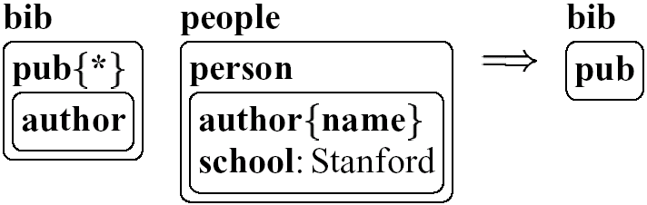
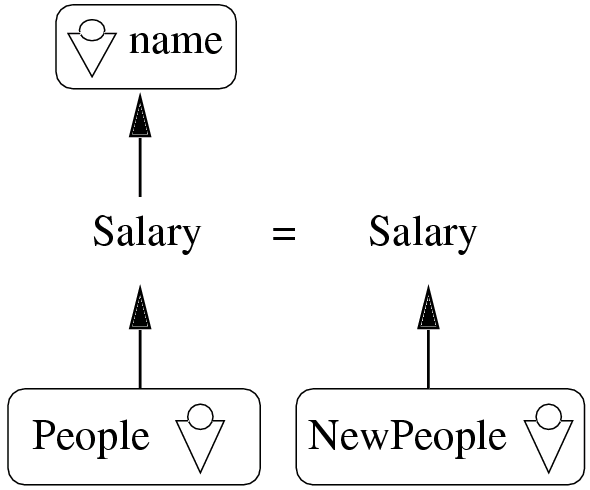
WG-Log is based on G-Log, a database language intended to query complex objects through the use of graphs and pattern matching. The patterns are explicitly based on schemas. A query consists of one or many graphs, each representing a rule. Opposed to other approaches like Xing found in [erwig00visual] and visXcerpt, the query and the construction part are integrated in one structure (a graph), while Xing and visXcerpt separate construction and query parts. The querying graph structure is spanned through thin or red lines, while the construction structure is spanned by green or thick lines. This indicates very clearly the relation of how the information flows between query and construction part -- they share the same nodes, making variables obsolete. A possible drawback is that complicated graphs could tend to be cluttered with many edges, but this has not been further investigated.
Due to schema use, the query patterns can be smaller than their hypothetical untyped equivalent. On the other hand, WG-Log is only applicable to schema based data, while semi structured data encourages the use of schema free data. This domain is covered by XML-GL.
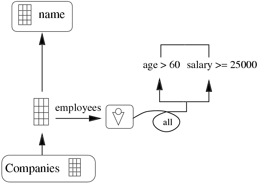
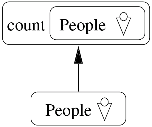
XML-GL uses pairs of graphs arranged horizontally and separated by a line to represent rules. Graphs consist of boxes with names inside, representing element names. Complex programs may consist of various rules. The graphs are used as query and construction patterns. Because XML data is tree structured, simple queries can be expressed with trees as query patterns. Graphs are used to model joins. Information is carried from the query side to the construction side by tag name match. This means that an element with a certain name in the query pattern is carried to the corresponding position in the construction pattern, where the same name occurs. Various constructs exist to use unnamed data and to overcome ambiguity. If e.g. a name occurs more than ones in a query graph, a line connecting the relevant query and construction node is used.
XML-GL is explained in more detail in [ceri99xmlgl].
2.3.1.2 About Stefano Ceri et.al - "XML-GL: A Graphical Language for Querying and Restructuring XML Documents"
In [ceri99xmlgl], XML-GL is presented as visual query and transformation language for XML. The use of XML-GL does not rely on the availabilty of schema information. If some kind of schema is available, editing and creating queries becomes easier, but the evaluation model of the language does not rely on a schema.
It is on the other hand possible to express schema information with XML-GL, with more expressive power than the DTD formalism provides, but no primitive type system for the textual information, as in XML-Schema, is available.
An XML-GL program is a set of pairs (at least one pair) of XML-GL graphs arranged horizontally, the left representing the query pattern and the right for the construction pattern. An XML-GL schema is an XML-GL graph enriched with extra constructs for conditions that are not mentioned in the context of query programs.
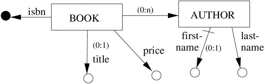
<!ELEMENT BOOK       (title?,price,AUTHOR*)>
<!ATTLIST BOOK
               isbn  CDATA  #REQUIRED>
<!ELEMENT title      PCDATA>
<!ELEMENT price      PCDATA>
<!ELEMENT AUTHOR     (first-name,last-name)>
<!ELEMENT first-name PCDATA>
<!ELEMENT last-name  PCDATA>
A graph consists of labelled boxes representing elements. Their hierarchical structure is modelled by directed edges. Patterns described this way can be used for querying as well as for schema implementation -- a data instance is valid, if it matches with a pattern. To denote the relevance of order for child elements, the first edge is crossed by a short stroke. If the structure is an acyclic graph instead of a tree and it is used as query pattern, it can be interpreted as using a join: the "child node" with more than one ancestor indicate that the ancestors must share identical child nodes. Hence the join is expressed over the shared child node. This is also the case, if two trees share nodes. In a schema graph the edges are labelled with multiplicity information like edges of ER-Diagrams. Another special visualisation is used for nodes containing only textual content -- they are drawn as hollow circles. Filled circles depict attributes. The edges to those circles are labelled with the element name or the attribute name.
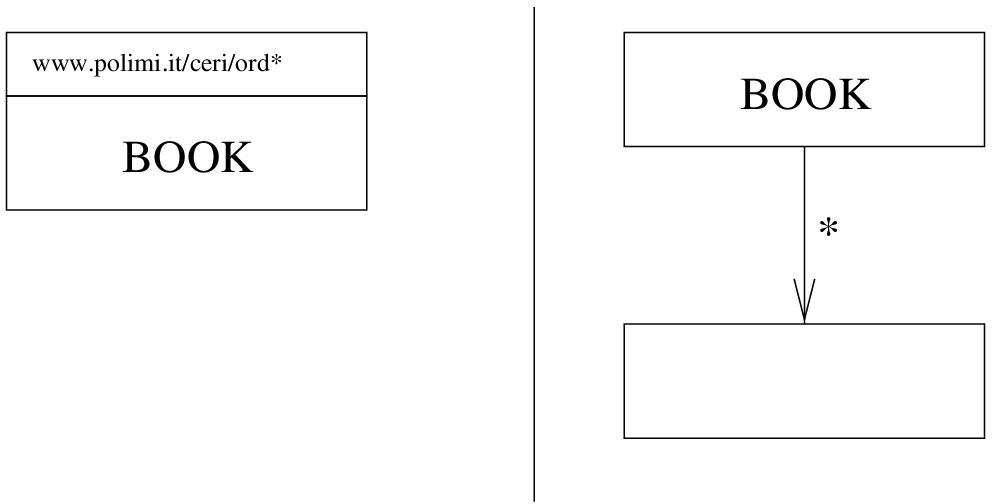
A feature used solely in schemas is an xor arch, crossing two edges. To model mixed content of plain text and elements, the elements and a text node circle are xor-ed. The edge to the textnode circle is labelled with "content" to indicate that it is not a text-only element. Therefore in this circumstance it is not possible to construct a text-only element called "content", a namespace mechanism that is actually missing in XML-GL, would be needed.
The base idea for the use of XML-GL graphs for querying has already been explained in the section about [comai00graphical]. Further constructs are explained now. There are three kinds of construction primitives for aggregation purpose:
- Plain boxes: They are used to construct elements. The elements have the same name as the box. For each element the query pattern has matched, an element is constructed by the box the query pattern is attached to.
- Triangles: They simply list all the matched elements from the query part they are attached to explicitly or by name.
- List icons: They react as a kind of combination of both, plain boxes and triangles, by aggregating the matched elements according to an additional grouping condition explicitly related to by an edge.
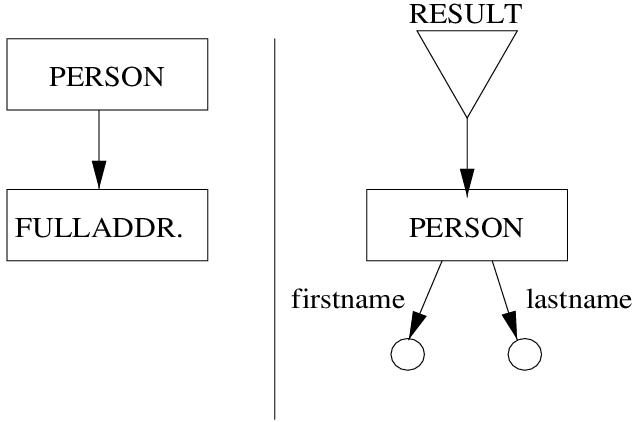
Further constructs are available for nesting and unnesting of content, which are powerful tools to prevent recursive queries that are not expressible in XML-GL. Nevertheless it does not seem to be possible to express queries about the structure of the queried data with the constructs presented, which is usually a simple task with recursion.
2.3.2 GraphLog
Graphlog as presented in [consens89expressing] has a lot in common with WG-LOG mentioned earlier. WG-LOG is based on GraphLog. GraphLog is visual language inspired by DataLog which are variable free Prolog programs. GraphLog is intended to query and transform graph structures, having hyperdocuments in mind -- the WWW was not established at the time of writing that article, but the concept of hyperdocuments was already known. In GraphLog it is possible to express patterns based on named directed edges between nodes. As in WG-LOG there is no structural separation of construction patterns and query patterns -- queried and derived arrows are distinguished through their line width: thin edges depict query edges while thick edges depict so called virtual edges. The nodes between the edges are unnamed circles. Attribute values can be shown as rectangles with their content inside (the arrow pointing to an attribute is labelled with the name of the attribute). A doubly circled node depicts an all-quantified node.
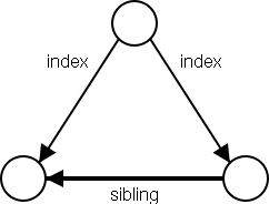
A third edge type is introduced in GraphLog -- a dashed edge. It is used to express a regular path expression. Such an edge may therefore substitute arbitrary other edges. An edge may also be crossed-out to indicate a negation. No such edge is allowed in the physical or virtual graph.
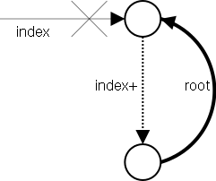
2.3.3 VXT
VXT is a visual language integrated into an interactive runtime and editing environment. Its main purpose is transformation rather than querying. It has been presented in the two publications [pietriga01xvt2] and [pietriga01xvt].
2.3.3.1 VXT: Visual XML Transformer
The article [pietriga01xvt2] is a short summary of VXT. VXT is a pattern based language. Because the emphasis is on transformation rather than on querying, some commonly used query language features, like aggregation, are not covered.
The roots of XVT can be found in XSLT. Several rules provide a template mechanism. A rule consists of a query and a construction part. Information matched on the query side is collected through links with slots on the construction side. The links can be typed as copy-, textual extraction- or template application-relation.
The XML visualisation is a so called visual treemap representation. Elements are displayed as horizontally aligned nested boxes. Above the box a label indicates the element name. Text nodes are represented as diamond shaped boxes, attributes as triangles.
VXT: A Visual Approach to XML Transformations
The article [pietriga01xvt] presents VXT in more detail, compared with [pietriga01xvt2]. The additional aspects covered here are related to document type definition, further language constructs and the translation of VXT programs into XSLT.
A very intersting aspect mentioned is, that very little extension is nessecary to use this visualisation mechanism as document type definition formalism. The proposed extensions are:
- conditions or choices: choices are modelled by stacking the different choices vertically.
- zero or one occurence: Those elements are surrounded by a dashed box.
- zero or many occurences: Like zero or one occurence those elements are surrounded by a dashed rectangle, but a second empty dashed rectangle is attached to its right side by a short dashed line.
- one or many occurences: in this case the same notation as zero or many occurences is used, except that the left dashed box is drawn with a solid line.
The schema definition presented this way can be used as translucent overlay or template mechanism inside the editing window to support easier transformation writing.
2.3.4 BBQ
As presented in [munroe00bbq], BBQ is an interactive visual browsing and querying environment. Its querying functionality is back-ended by the textual query language XMAS [papakonstantinou99framework]. Querying in BBQ is schema-driven using XML DTDs, but at the same time the user is encouraged to browse the schema and data. A BBQ session consists of query cycles. A cycle is made up of query specification and query execution. The user may refine the queries until the desired result is achieved. To make this approach feasible, a lazy approach to the implementation of the query engine and browser is suggested.
Visualisation of queries and results is based on standard tree visualisations, as found in all modern visual user interface tool kits. Various icons are used to depict the different node types of schemas and results. The Java toolkit Swing is used for an implementation explained in the article. The editing of queries is based on cut/copy and paste as well as drag and drop.
A query in BBQ consists of a query and a construction part. The query part is a tree view of the DTD from the database to be queried. Every node can be refined through use of textual constraints. Joins are built through use of drag and drop. This way only equijoins can be expressed. Joins are indicated by textual annotation on the node's visual representation. Constructors are located in a second tree view. Nodes in constructors are either created as new nodes or are dragged from the query tree view. Dragging a query node to a construction tree indicates that the nodes matching the query node at execution time are included in the corresponding location of the construction tree. The naming of a dropped query node in a construction tree is based on a path notation of the query node and indicates its path to the root of the schema.
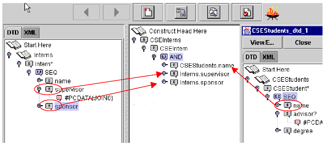
The result of executing the query is presented in a tree for browsing. The textual representation of the corresponding XMAS query is also presented. A back and forward button, as known from all modern web browsers, can be used to access all query cycles of a session.
2.3.5 QURSED
The QURSED project [petropoulos02qursed] provides a tool for authoring web-based query forms and reports. To create the query forms, the developer may use any web page editor. These forms are back-ended by a query language called TQL (tree query language). An editor for tying query forms to TQL programs (the QURSED editor) is presented. At this level the developer has to cope with the tag structure of the query forms, to provide bindings to constructs of the TQL program. By populating the form, the user ties concrete values to variables in the TQL program and the query can be executed.
A TQL program is a tree consisting of constant nodes (they are labels that match elements in the queried XML tree), node name variables, literal variables (at leaf level), AND and OR constructs providing the ability to construct conditions based on comparison of variables to literals or to other variables. In the end a TQL program is translated into a XQuery program producing the result.
The TQL program editor is a classical tree view. The tree view used in this project is Swings JTree found in Java with nodes representing the language components. The editor model is the default behaviour provided by the windowing toolkit used to implement the TQL program editor. Like Xcerpt TQL is a pattern based language. Compared to Xcerpt, TQL is much simpler to implement, but the language is also much more restricted. Programs written in TQL tend to be longer and less readable then Xcerpt programs.
2.3.6 Xing
Xing is a form-based interface to express XML queries and transformations by so-called "document patterns", presented in the articles [erwig00visual] and [erwig-xml2000]. The form based character is motivated by the fact that forms often represent nested boxes of sections, questions and answer fields. The main idea is to let the user draw samples, of the data he expects from a query to be returned. Optionally a construction pattern of the structure for the resulting document may be provided. These two document patterns together are called a document rule. To transport information from the querying pattern to the construction pattern, variables (so called aliases) are used.
The definition of this system was based the on following design goals:
- do not define a(nother) textual language,
- avoid XML syntax,
- use a simple and intuitive visualisation of XML,
- employ pattern matching,
- facilitate restructuring,
- keep the system simple and intuitive.
Based on these constraints, it was nescessary to define a visualisation of XML. This is called the document metaphor which is strongly influenced by documents like product descriptions and forms. XML documents are visualized as follows:
- XML elements are represented by boxes (with rounded edges),
- tag names are written in bold font above the corresponding element on the left,
- elements containing only plain text are shown as the (bold) tagname followed by the text on the same line and both separated by a colon,
- attributes are displayed like the former abbreviated elements, except that the attribute name is not bold faced,
- elements containing text mixed with other elements (like HTML/XHTML documents) are not supported,
- XML name spaces are neither supported.
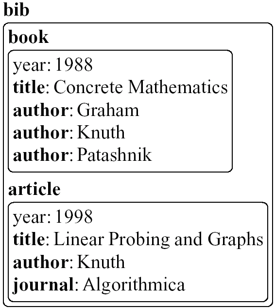
Document patterns are built as instances of the document metaphor. Further elements are:
- Regular expressions: regular expressions (and therefore also simple wildcards) may be used instead of tag names.
- Aliases: matched patterns may be enclosed in curly brackets prefixed by a name. It is possible to refer to this name in the result pattern.
- Or-patterns: or patterns are shown like or-statements in regular expressions - the components are arranged horizontally and joined by a vertical bar.
- Deep queries: Deep queries are able to match at arbitrary depth in the document tree below their occurence. They are depicted as an ellipsis prefixed to the pattern that is used for the deep query.